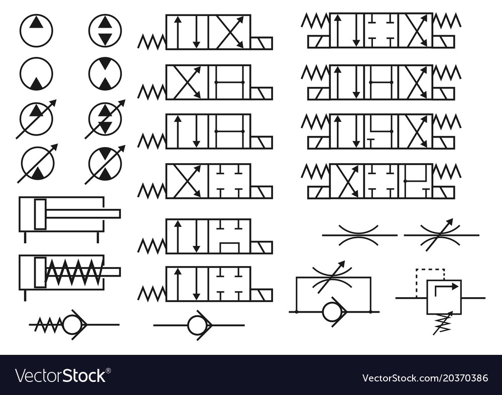
Pneumatic Symbols Chart
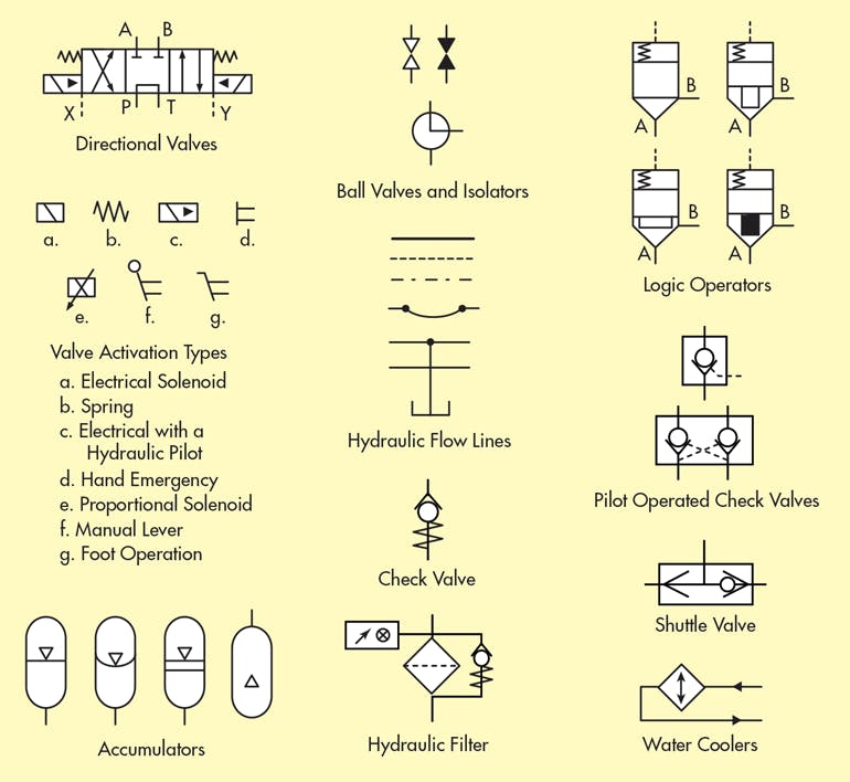
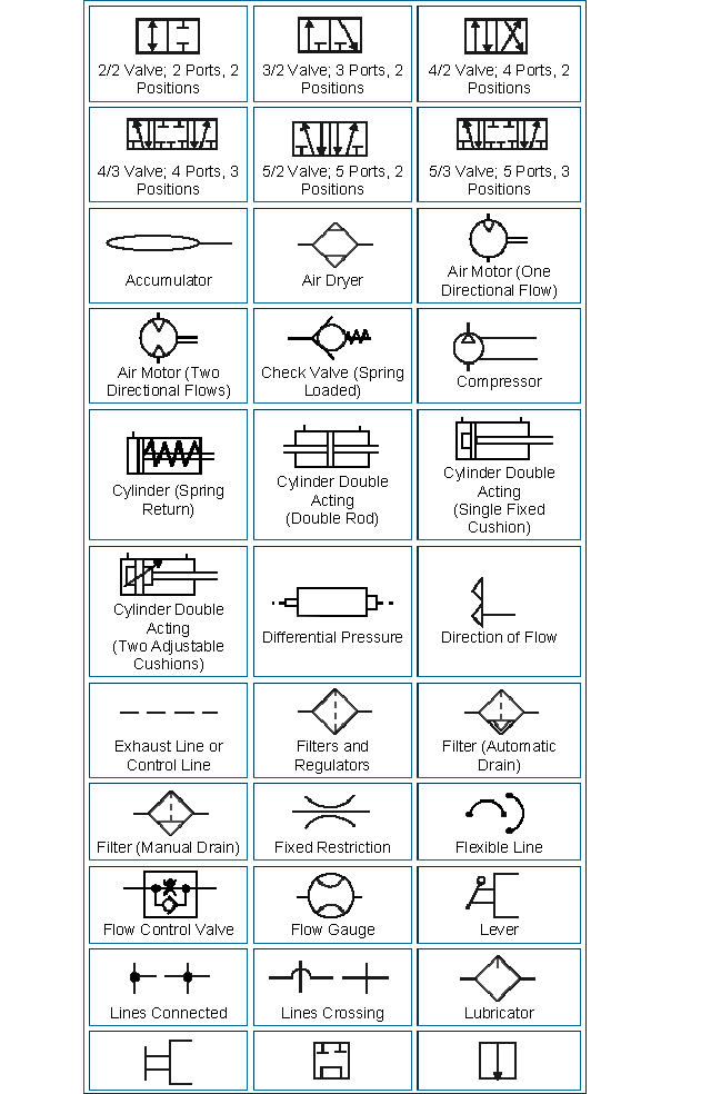
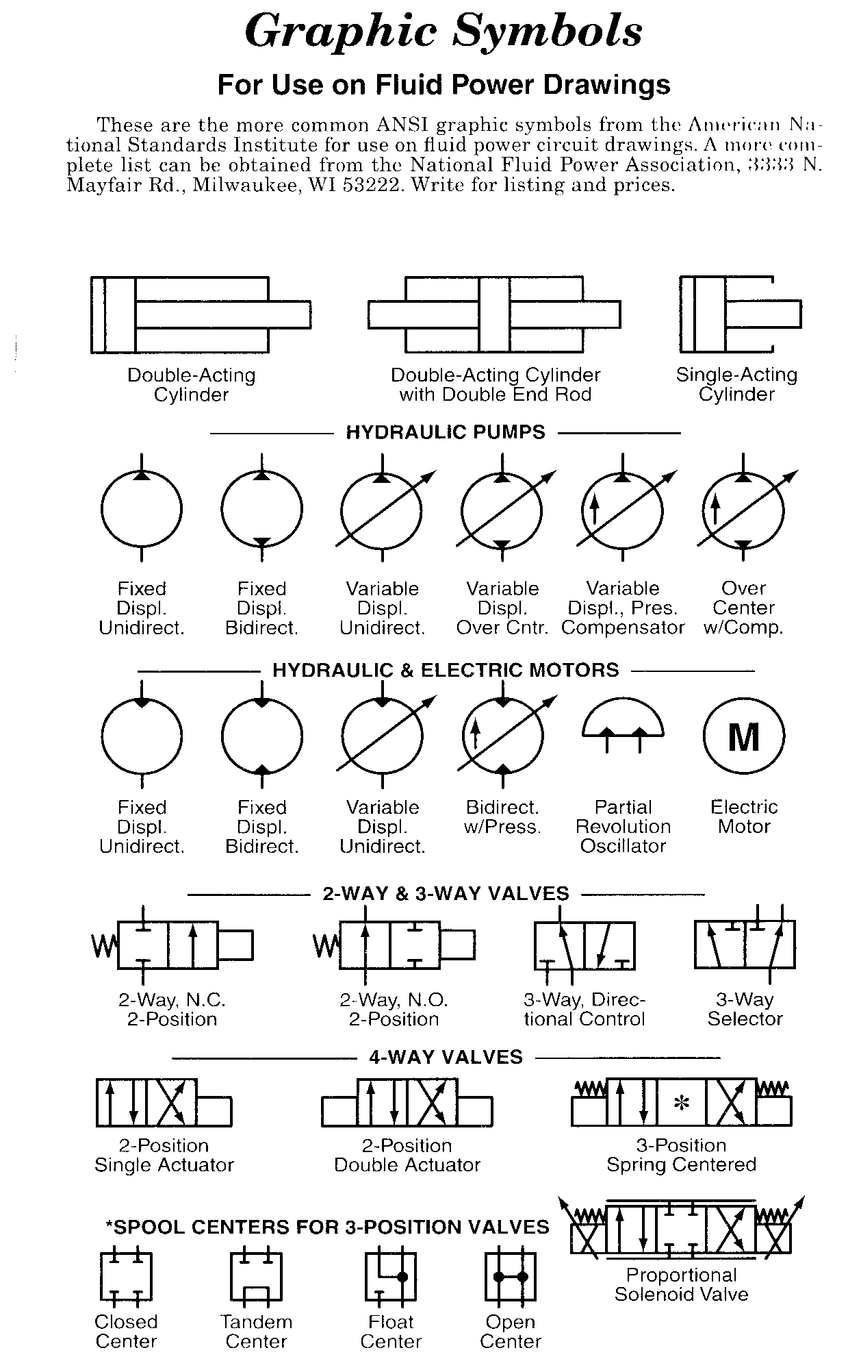
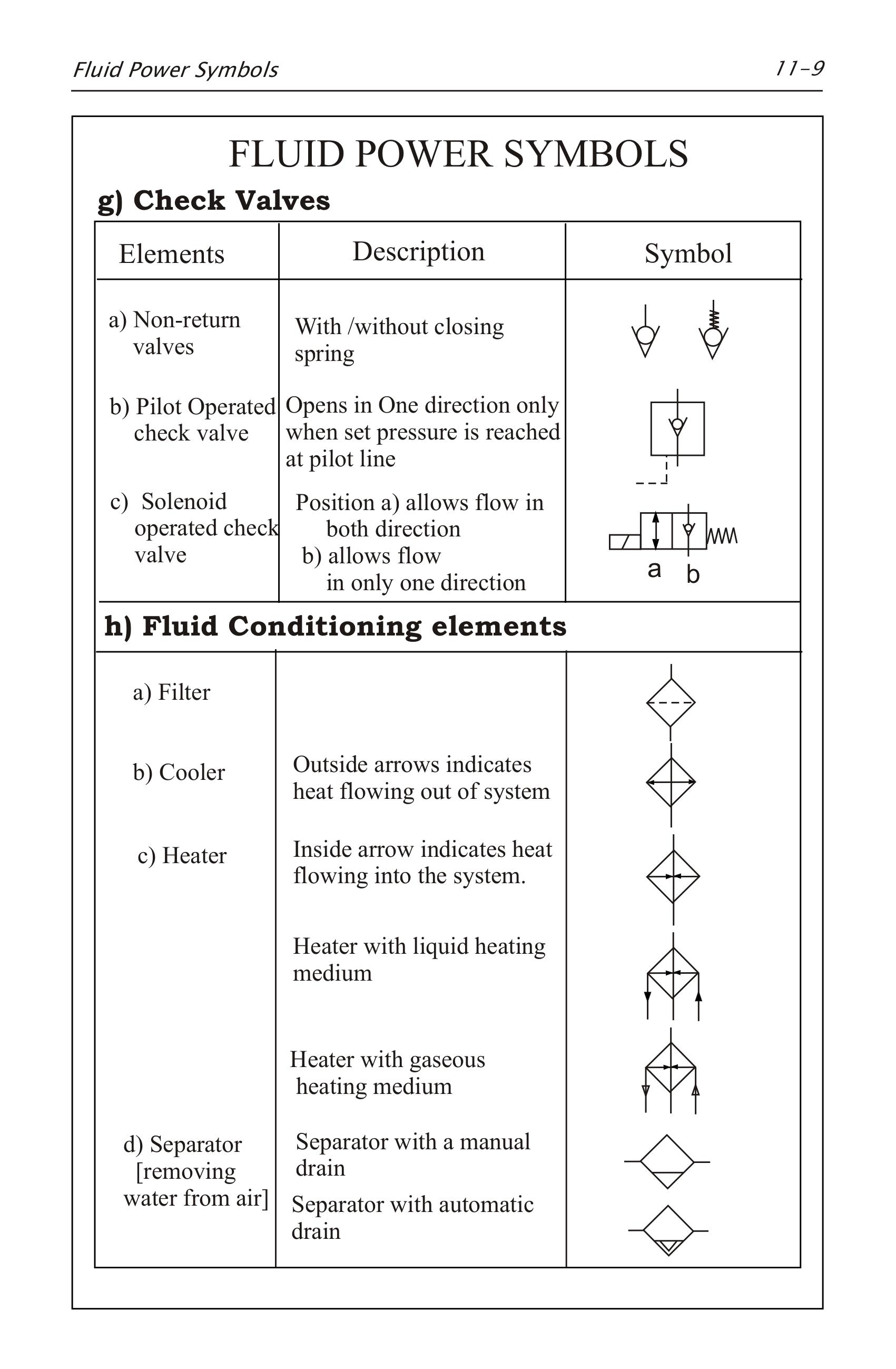
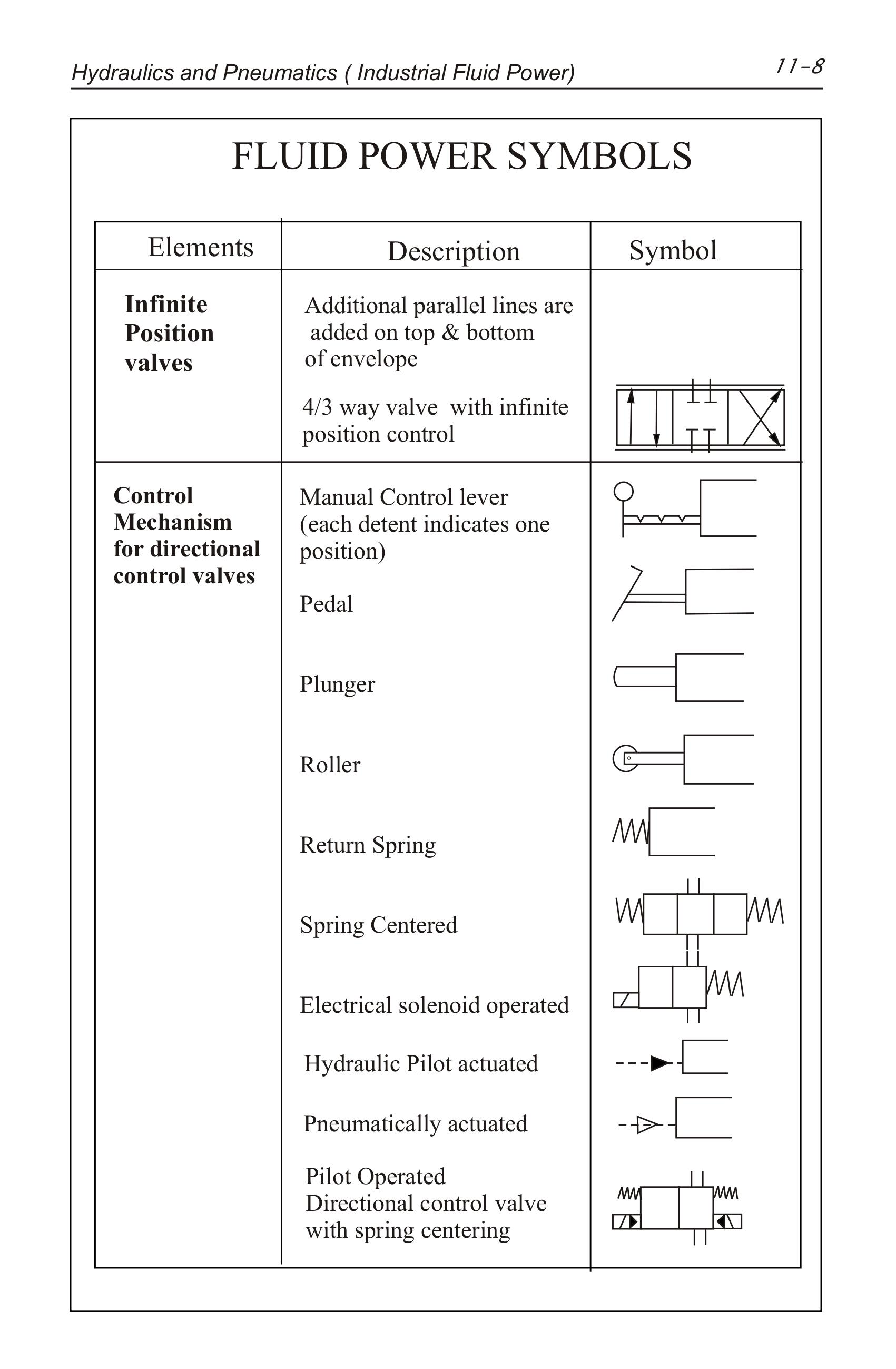
Pneumatic Symbols Chart - Web symbols show the methods of actuation, the number of positions, the flow paths and the number of ports. They are commonly represented with symbols. These pneumatic systems perform a myriad of tasks in automated. Web the most common pneumatic schematic symbols include flow arrows, actuators, directional control valves, pressure regulators, pressure relief valves, flow. Web pneumatic diagrams representing pneumatic systems have defined ways they are represented. Here is a brief breakdown of how to read a symbol: Web pneumatic symbols for system diagrams and component identification contents z z z z z z z z standards b i symbols basic b l functional elements flowlines connections. Web understanding circuit symbols directional air control valves arethe building blocks of pneumatic control. Web pneumatic power transmission methods are often the best way to move parts and tooling in industrial machines. Web all the symbols you need to design your pneumatic circuit in.dxf format. Web pneumatic diagrams representing pneumatic systems have defined ways they are represented. Web the most common pneumatic schematic symbols include flow arrows, actuators, directional control valves, pressure regulators, pressure relief valves, flow. These symbols are fully explained in the usa. Symbols (marks) each heading is shown with symbols in order to make it easier to see. To posltlon quick exhaust shuttle symbol description. These pneumatic systems perform a myriad of tasks in automated. Web understanding circuit symbols directional air control valves arethe building blocks of pneumatic control. Web pneumatic power transmission methods are often the best way to move parts and tooling in industrial machines. Scan through and easily download the one you need. Pneumatic symbols are the graphical representations of the components in pneumatic diagrams, which will make it possible to identify and. Web what are pneumatic symbols? Symbols (marks) each heading is shown with symbols in order to make it easier to see. These pneumatic systems perform a myriad of tasks in automated. Web pneumatic diagrams representing pneumatic systems have defined ways they are represented. Web pneumatic symbols for system diagrams and component identification contents z z z z z z z. Web all the symbols you need to design your pneumatic circuit in.dxf format. Take a look at our comprehensive list of common symbols for use in circuit diagrams, available to download in pdf format. How do i select a pneumatic symbol? These pneumatic systems perform a myriad of tasks in automated. Symbols representing these valves provide awealth of information. Web the chart above shows a good representation of common symbols and more is outlined below. Web pneumatic power transmission methods are often the best way to move parts and tooling in industrial machines. Scan through and easily download the one you need. Symbols (marks) each heading is shown with symbols in order to make it easier to see. These. Web symbols show the methods of actuation, the number of positions, the flow paths and the number of ports. Take a look at our comprehensive list of common symbols for use in circuit diagrams, available to download in pdf format. Web all the symbols you need to design your pneumatic circuit in.dxf format. Web pneumatic power transmission methods are often. These symbols are fully explained in the usa. Web pneumatic symbols for system diagrams and component identification contents z z z z z z z z standards b i symbols basic b l functional elements flowlines connections. Take a look at our comprehensive list of common symbols for use in circuit diagrams, available to download in pdf format. International system. Web symbols show the methods of actuation, the number of positions, the flow paths and the number of ports. Web types of symbols commonly used in drawing circuit diagrams for fluid power systems are pictorial, cutaway, and graphic. Web the chart above shows a good representation of common symbols and more is outlined below. Web what are pneumatic symbols? Here. International system of units (si) this catalog is written with si units. Learn how to interpret and use these symbols in your pneumatic schematic. These symbols are fully explained in the usa. Here is a brief breakdown of how to read a symbol: Web pneumatic diagrams representing pneumatic systems have defined ways they are represented. Learn how to interpret and use these symbols in your pneumatic schematic. Scan through and easily download the one you need. To posltlon quick exhaust shuttle symbol description. Web pneumatic diagrams representing pneumatic systems have defined ways they are represented. Web what are pneumatic symbols? Web pneumatic diagrams representing pneumatic systems have defined ways they are represented. Pneumatic symbols are the graphical representations of the components in pneumatic diagrams, which will make it possible to identify and. Web all the symbols you need to design your pneumatic circuit in.dxf format. These symbols are fully explained in the usa. Web pneumatic power transmission methods are often. These pneumatic systems perform a myriad of tasks in automated. Web download a pdf with pneumatic schematic symbols, including valves, cylinders, motors, and more. Web all the symbols you need to design your pneumatic circuit in.dxf format. They are commonly represented with symbols. Learn how to interpret and use these symbols in your pneumatic schematic. Web understanding circuit symbols directional air control valves arethe building blocks of pneumatic control. Here is a brief breakdown of how to read a symbol: Web the chart above shows a good representation of common symbols and more is outlined below. Symbols representing these valves provide awealth of information. Web the chart above shows a good representation of common symbols and more is outlined below. Symbols (marks) each heading is shown with symbols in order to make it easier to see. Web pneumatic power transmission methods are often the best way to move parts and tooling in industrial machines. Recognizing and understanding schematic symbols will enable you to. Web symbols show the methods of actuation, the number of positions, the flow paths and the number of ports. Web types of symbols commonly used in drawing circuit diagrams for fluid power systems are pictorial, cutaway, and graphic. Web the most common pneumatic schematic symbols include flow arrows, actuators, directional control valves, pressure regulators, pressure relief valves, flow. International system of units (si) this catalog is written with si units. Web download a pdf with pneumatic schematic symbols, including valves, cylinders, motors, and more. How do i select a pneumatic symbol? Web pneumatic symbols for system diagrams and component identification contents z z z z z z z z standards b i symbols basic b l functional elements flowlines connections. These pneumatic systems perform a myriad of tasks in automated.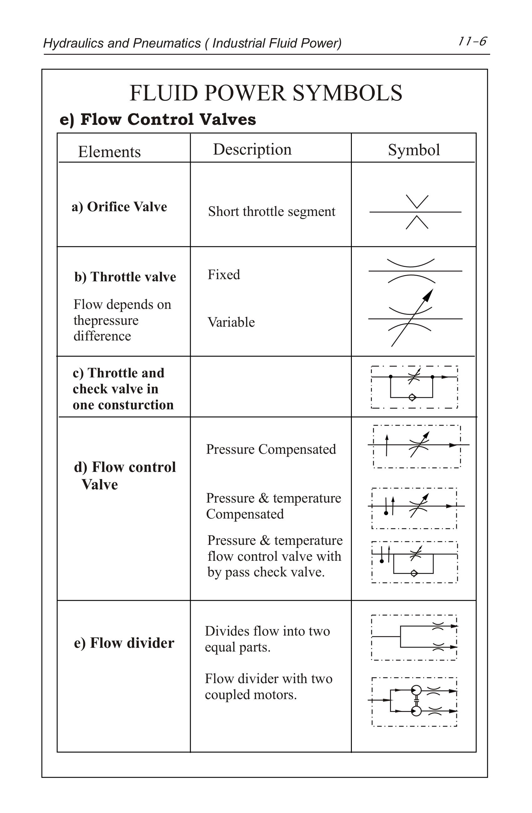
Pneumatic Symbols Chart With Meanings
Hydraulic Schematic Symbols Chart
Pneumatic Symbols Chart With Meanings
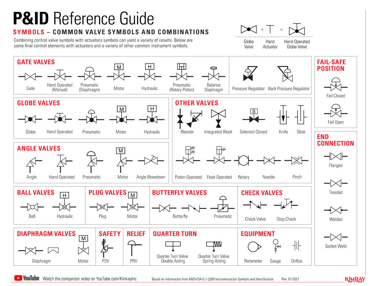
What’s the Difference Between Hydraulic Circuit Symbols? Machine Design
Pneumatic Symbols Chart With Meanings

Pneumatic Schematic Symbols Chart Wiring Diagram
Hydraulic Schematic Symbols Chart
Pneumatic Symbols Chart With Meanings

Pneumatic Symbols Chart With Meanings
Pneumatic Symbols And Functions
Take A Look At Our Comprehensive List Of Common Symbols For Use In Circuit Diagrams, Available To Download In Pdf Format.
Learn How To Interpret And Use These Symbols In Your Pneumatic Schematic.
They Are Commonly Represented With Symbols.
Scan Through And Easily Download The One You Need.
Related Post: